Reading Signals
There are only two main methods the cells of our bodies use to communicate: chemical signaling and electrical signaling. For human-robot interfacing, reading the body's electrical signals is preferred for several reasons. First, electrical signals sent through the body are fast and produce a near instantaneous result. Second, electrical signals may be measured from the outside of the body so instrumentation used to read intention can be non-invase. And third, electrical signals are directly compatible with computers and other electrical hardware used to filter and interpret the body's signals.
Electrodes are used to measure physiological potential. There are different electrodes for different applications but each operate on the same basic principle: measuring a potential difference between two points. Take for example the measurement of potential from the scalp. Below is a diagram of a basic two channel electroencephalograph circuit. The voltage at two variable nodes on the scalp is measured in respect to a reference node placed on the right ankle of the subject.
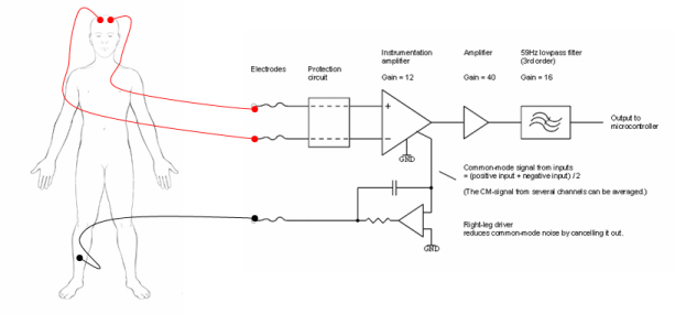
Figure 1. 2-Channel Electroencephalograph Circuit
The signals taken from the scalp may be fed into a microprocessor to perform initial data formatting. From the microprocessor, data may be sent over a serial connection to a computer for further analysis. General algoirthms used to interpret a human intention to move or speak or otherwise are discussed in the Interpreting Signals section. Similar hardware is used to measure potential changes in the muscles.
Figure 2. Microcontroller-Computer Connection
Current research favors certain arrangements of electrodes on the body to produce interesting and clinically useful signals for human-computer interfacing studies. These electrode arrangements fit into two main categories: brain-based systems and muscle-based systems. In general, signals measured directly from the brain are more indirect and require more rigorous processing than signals meausred from muscles or motor neurons.
Brain Based Systems:
Discerning a meaningful signal from the brain is often metaphorically likened to attepting to isolate from a symphony the sound of a single violin. The task is difficult for two reasons. First, it is hard to get to brain signals directly—the skull has resistive and capacitative properties that act to attenuate and distribute electrical signals. Skull resistance and capacitance depends on the orientation of cortical tissue , skull thickness ,surrounding tissues in the skull like cerebrospinal fluid or blood, and scalp skin resistance that may be continually altered due to sweat production [15] . And second, once the signals from the brain are read, they are often difficult to interpret. Following, there are three main types of measurement systems used in brain-computer interfacing that are robust enough to overcome these challenges: electroencephalographic systems, electrocorticographic systems, and single unit systems.
EEG Systems:
Electroencephalography (EEG) is the measurement of biological potential from the scalp. The location of electrodes placed on the scalp determines the type of signal that will be read by the EEG circuitry. In human-computer interfacing studies, three types of EEG signals are common: sensory-motor rhythms, slow cortical potentials, and P300 evoked potentials.
P300 Evoked Potentials
Scientists have shown that when an important visual, auditory, or somatosensory stimuli appears to a person among many random stimuli, that significant stimuli causes a positive potential spike over the parietal cortex. Because it occurs over the parietal cortex and usually lasts about 300 ms, this recognition spike is usually referred to as a P300 evoked potential. This interesting physiological event is used in some Brain-Computer Interface (BCI) systems to allow a user to communicate by selecting signals from a screen that presents random stimuli. Below is a 60 Minutes story that features a P300 evoked potentials system.[10,17,19,39,41]
Slow Cortical Potentials
Slow cortical potentials are potential changes over a large area centered at the top of the head that vary in polarity and amplitude based on a person’s thoughts. Negative slow cortical potentials are usually indicative of movement or cognition while positive cortical potentials are usually associated with inactivity. Scientists Birbaumer, Kubler et al. have developed a system using slow cortical potentials called the Thought Translation Device that allows paralyzed individuals to perform simple tasks on a computer. [9]
Sensory Motor Cortex Rhythms
Electrical signals read from the area of the scalp directly over the sensory motor cortex of the brain provide particularly interesting information for BCI systems used to control robotic prosthetics. At rest the normal human brain displays activity in the 8-12 Hz and 18-26 Hz frequency bands, called the mu and beta rhythms, respectively. When a person thinks about a moving a certain body part, activity in the mu and beta frequency ranges decreases dramatically in the area of the sensory motor cortex that corresponds to that body part. What makes these neural signal patterns important to Human computer interfacing studies is that the mu and beta frequency drop occurs even when the planned movement is not executed—that is, the signals are still observable in paralyzed patients like those with advanced ALS or spinal cord injury. BCI systems based on these mu and beta rhythms have been used to give disabled patients neural control over simple prostheses and two dimensional computer cursor systems. [15,26,28]
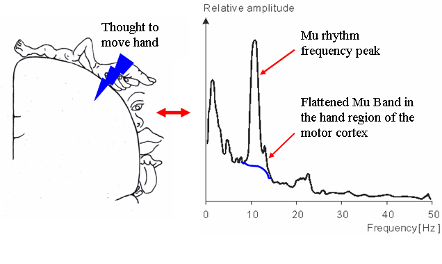
Figure 3. Effect of Motion Planning on Mu Rhythms
With any electrode arrangement, electroencephalography is advantageous because it is totally non-invasive, low cost, and easy to setup/use. This is why EEG is the most widely used cortical potential measurement technique. However, the resolution of electroencephalography is rather poor at 3-5 cm, a factor that could prove to limit the applicability of EEG to brain-computer interface applications. In the literature, mapping from electrical currents in the brain to potential fields on the scalp is referred to as the forward EEG problem, and mapping the source of read potential fields is known as the reverse EEG problem. Current research in EEG technology involves developing more precise conductivity models for the brain and skull that take into account the anisotropy of these tissues so that the reverse EEG problem can be more precisely solved. This research may lead to the development of new higher resolution EEG techniques that would make the technology more applicable to BCI studies that require precise information.
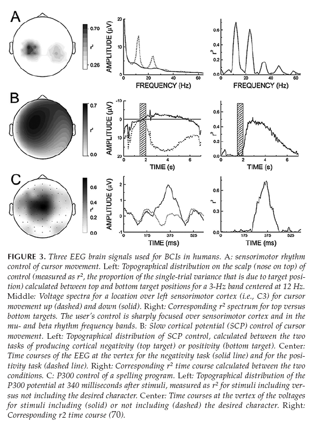
Figure 4. Different EEG Patterns [15]
ECoG Systems
Electrocorticography, or ECoG, is the measurement of the brain’s biopotential from within the skull. In order to obtain an electrocorticographic signal, a variable electrode or electrode array must be surgically placed epi- or subdurally (but not within the brain’s inner membranes). For human-computer interfacing purposes, ECoG electrodes are usually placed over the sensory-motor cortex of the brain to record signals that correspond to planned movement. In this way, the objectives of ECoG are very similar to those of EEG. However, despite the similarity in electrode location, ECoG signals have proven to be considerably different from EEG sensory-motor signals. Compared to EEG, electrocorticography has greater spacial resolution (0.125 cm vs. 3 cm EEG), a greater frequency bandwidth (0-1000Hz vs. 0-40Hz EEG), greater signal-to-noise ratio, and a larger magnitude response (0.05-1.0 mV vs. 0.01-0.2 mV EEG) [15] . Most notably, because of the greater frequency bandwidth, ECoG is capable of picking up the gamma rhythm (>30Hz) along with the mu and beta rhythms that are detected from outside of the skull. Whereas the low frequency mu and beta rhythms are thought to be the result of thalamocortical circuits, gamma rhythms are thought to be the result of localized cortical circuits—making information decoded from the gamma rhythm more precise and localized. While ECoG technology is rather new and progress is slow due to the risk associated with implanting ECoG electrodes, the gamma rhythm has none the less provided an exciting prospect for researchers working to develop more precise and intuitive brain-controlled prostheses.
Single Unit Systems:
Systems that record the electrical activity of individual neurons are known as single unit systems. Single unit systems require that an electrode or an array of electrodes be implanted into the cortical tissue of the brain. Two types of electrodes currently used in single unit research are neurotrophic electrodes and penetrating electrode arrays.
Neurotrophic Electrodes
Scientists Kennedy and Bakay developed a neurotrophic electrode for the measurement of single-unit potentials. The electrode consists of a tiny glass cone that contains embedded neurotrophic factors and electrocal leads to the outside of the skull. When the cone electrode is implanted into the brain, the neurotrophic factors encourage native neurons in the implant region to grow into the cone. Then, whenever the target neurons fire, the electrical pulses are transmitted from the leads in the glass cone to external hardware. This type of single unit system has been implanted into the Broca’s (speech) area of several advanced stage ALS patients to enhance speech by identifying the specific neural firing patterns that correspond to different speech producing sounds. [15]
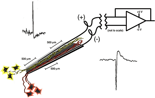
Figure 5. Neurotrophic Electrode [15]
Electrode Arrays
Mircro-electrode arrays offer another method by which single-unit potential may be measured. Micro-electrode arrays may have tens to one hundred electrodes protruding from a small chip. The array is implanted directly into the cortex to measure the electrical potential from a small subset of neurons. Often in brain-computer interfacing studies, the electrode array is implanted into the motor cortex to allow for the interpretation of planned movements. An electrode array of this type is used the in Braingate system discussed in the 60 minutes Brainpower episode in the Media section. Compared to the other brain potential measurement modalities used to capture signals from the motor-cortex, the penetrating electrode array is the most specific and allows for complicated movement commands to be interpreted from received signals. This specificity makes learning to use the system more intuitive. A video of a primate using an implanted electrode array to control both the position and velocity of a robotic arm can be viewed below. [15]
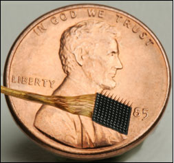 Figure 6. BrainGate Electrode Array |
|
Of all the brain potential measurement techniques, penetrating electrode array systems are by far the most precise. However, currently these systems have a major flaw—biocompatibility. Current single-unit electrodes only work for about a year after they are implanted because the body’s foreign body response causes an insulating sheath of glial and stellate cells to encapsulate the electrode and block electrical impulses from being detected. What’s more, due to the highly vascularized structure of the brain, it is nearly impossible to implant a penetrating electrode or electrode array without rupturing some vessels and causing minor damage at the implantation site. Because of the damage caused at implantation and the health risks associated with brain surgery, repeated implantations are unfavorable. Currently researchers are looking for ways to stop the foreign body response, including adding growth factors to the electrode, or continually pumping drugs into the area around the electrode to prevent adverse reaction. [15]
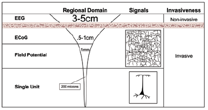
Figure 7. Electrode Depths [15]
Muscle Based Systems:
For disabilities that leave most of the body functional, like amputations, the brain is not the only source of intention information—signals traveling from the brain to the nerves that would have innervated the body part that was lost can also be intercepted and used as control signals Also, a techonology called targeted muscle reinnervation (TMR) has become a particularly significant modality for obtaining signals of intent.
Residual Limb Myoelectric Signaling (MES)
If an amputee has a significant residual limb, they may be fitted with a system that reads contractions in the residual limb and transforms this information into movement of a robotic prosthetic. These myoelectric prosthetics are currently commercially available from orthodics companies like Fit-Well and Advanced OrthPro. Further research into myoelectric prosthetics involves developing signal processing methods to get more information out of a single contraction. For example, scientists Hudgins el al. discovered that the electrical variations read in the initial stages of muscle contraction carry additional intention information that can be used to differentiate between the movements of different joints in a prosthetic. [24]
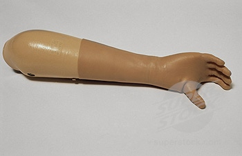
Figure 8. Myoelectric Arm
Targeted Muscle Reinnervation (TMR)
In targeted muscle reinnervation, the residual nerves of a lost limb or body part are rerouted to a muscle that was rendered biomechanically non-functional at amputation. For example, if the left arm was amputated at the shoulder, the nerves that once went to the right arm could be rerouted to the non-functional left pectoral muscle. Then, when the amputee imagines moving his/her amputated arm, the action potentials traveling down the nerve that once innervated the arm would go to the left pectoral muscle and cause contraction. This contraction could then be measured by a surface electromyogram (EMG). Because the potentials due to contraction are greater in amplitude than the original action potentials that caused the contraction, the reinnervated muscle effectively acts as a biological amplifier. Using EMG, specific contraction patterns can be mapped to intended movements and used to control robotic hardware. Researchers have found that the central motor control system can send complex efferent commands for a missing limb even without peripheral feedback from the limb, and without retraining the pathways involved. Targeted muscle reinnervation is advantageous over residual limb myoelectric signaling because it is intuitive and does not require significant residual muscle groups. [23,45]
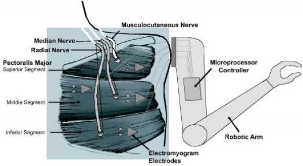
Figure 9. Targeted Muscle Reinnervation [23]
